Nikon D Series Lightning Trigger with Arduino

Taken from inside garage
I wanted to make a lightning trigger for the D40 camera to capture some of nature’s most beautiful displays. I also thought it would interesting to capture some fireworks this 4th of July. So off to google I went. I saw several projects that pointed me in the right direction but I needed to get them all together. I started out with the code required to activate the remote shutter for the Nikon. I found some code here: Thing-a-Day Site(code didn’t work) . The code on the page had some issues compiling. I then followed the replies and I saw a poster with his own code that links to ilpleut.be. I followed the link that the code at ilpleut.be (code that worked) looked very elegant and complete. So i decided to try it. It worked, and as advertised, every ten seconds it triggered the Nikon. The only thing needed was to add the detector mechanism.
Lightning Detector:
**VERY IMPORTANT** For lightning safety visit: NWS Lightning Safety
I found a simple schematic to actually capture the sudden flash in light at this site. The schematic was simple and easy to build. They used a wired trigger for the Canon 3OD. For this project I am adapting it to trigger the Nikon D40 using the infrared transmitter.
Parts List
1 – 220 Ohm resistor (IR LED Current Limiter)
1 – 100k Ohm resistor (for Photoresistor)
1- Arduino (Purchase an Arduino: Modern Devices, Spark Fun, adafruit)
1 – Photoresistor (recommended) or Phototransistor
1 – Green or Red LED (Triggering Status LED)
1 – Potentiometer (optional if you use Version 1.1)
Wiring
Use the schematics below to wire the detector and IR Transmitter to the arduino. There are two versions available, one with an adjustable trigger setting and one that you can hard set in the code.
NOTE: You can modify the TRIGGER_THRESHHOLD value to get the best results for your situation. You can also add a delay to tweak the actual follow-on shots.
Camera Setup
To setup the Nikon you must go to Menu; Custom Setting Menu; Release Mode; Change to Quick Repsonse Remote. You must then Change the Remote on Duration setting, it can be setup up to 15 minutes.
The code below is complete. No additional libraries are necassary.
Version 1.0:
- Download Nikon Remote Lightning Arduino PDE File
- Schematic for the Nikon D Series Lightning IR Remote shutter
Important: If you want to add a potentiometer to change the value of the TRIGGER_THRESHOLD use the below links for the PDE file and schematic
Version 1.1:
- Download Nikon Remote Lightning with potentiometer adjustment arduino PDE
- Schematic for the Nikon Remote with Potentiometer adjustment
Thanks to Aurelien Antoine and Maurice Ribble!!
Project Pictures
(Includes submissions from other hobbyists)
Credit given below each image
-

- Lightning picture

-

- photodiode


-

- Submitted by Jim Martin

-

- Submitted by Jim Martin

-

- Submitted by Jim Martin

-

- Submitted by Jim Martin

-

- Submitted by Jim Martin

-

- Submitted by Jim Martin

-
- Submitted by Jim Martin

-
- Submitted by Jim Martin

-
- Submitted by Jim Martin

-

- Submitted by Jim Martin

-

- Submitted by Jim Martin

-

- Submitted by Jim Martin

-

- Submitted by Jim Martin

-

- Blog Author

-

- Blog Author

-
- Credit: Joe

-

- Credit: Joe

-

- Submitted by J Martin

-

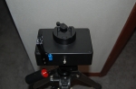
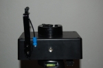
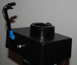
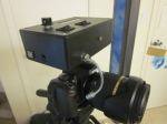
- Frank’s Completed Lightning Trigger


Great article ! thanks for taking the time to post all of this. I also have a D40, and now that I am retired, I am spending a LOT more time photographing storms. How are you triggering the camera to take the picture? Are you still working on developing the IR circuit to trigger the camera?
Thanks again,
Jim
@Jim: The code is complete with the IR trigger and detection. I am working on a simple schematic to outline how to connect everything to the arduino. In fact I used it on the 4th of July to capture some fireworks. It worked quite well, but I have yet tried it with lightning. We have had some recent storms but the conditions were not favorable to take photographs. One tip: the IR Sensor on the camera is on the left hand side looking at the front of the camera. You almost have to have it pointed straight on for it to trigger. I was able to get about four feet distance with moderate indoor lighting.
Jason,
Thanks for the quick reply! Can you post part numbers of the phototransistor and IR led that you used? I have a couple of ideas of how I want to “couple” the output of the IR LED to the front of the D40.
Can you contact me via email ( jimdmartin “at” embarqmail.com), or do you want to trade ideas here?
@Jim: Just posted the schematic in the original post. The phototransistor can be replaced with a photodiode (from a Glade Sense and Spray freshener) or a photoresistor (Radioshack project leftovers). I tested both and they have excellent response times.
As far as the IR LED, that came from an old universal TV remote that I re-purposed for this project. I believe in recycling parts!
I tested it by taking a picture of the lightning trigger using flash(to simulate lightning) and the status LED was lit in the photograph. That tells me that the trigger was activated within the time span of the flash and exposure from my other camera. That should be more than fast enough to take a picture of lightning.
We can trade ideas here so that others may learn. I am still learning myself and I have found a lot of value in other people’s comments and questions.
It would be really interesting if people that used this project link the photos here. I would love to see some lightning pictures as a result of this.
Thanks for uploading the schematic. Very simple, and anyone should be able to build this one! I also like to “re-purpose” parts, and as such, have quite a little treasure trove of odds and ends components. Would it be possible to replace the 220 ohm IR LED resistor with something like a 10-turn pot, maybe in the range of 0-500 ohms, in order to be able to adjust the output strength of the IR LED, and also maybe substitute a 0-200K pot on the phototransistor, to adjust overall light sensitivity?
I will be building my Arduino based detector in an enclosure, and want to be able to mount the phototransistor either on the exterior of the box, or behind a “window”, and then couple the output of the IR LED through a fiber optic “tube”, which will run from the enclosure, up to the camera, and attached to the camera body just below the IR sensor. I do know that I can remove the “lense” of another IR LED, and by mounting it to the end of the fiber optic tube, it will act as a reflective “dome”, and I won’t have to aim the fiber optic tube directly at the camera sensor. I’ll see if I can sketch up something that shows what I am talking about, but I don’t think I will be able to post it here.
Jason,
Sorry for all the posts, but what is the proper wavelength for the IR LED? 875 or 940nm ? I tried to locate the specs on the IR sensor in the D40, but am not having much luck….
@Jim: No problem, I believe either one will work. I read somewhere that 800-1000nm will work.
Thanks, Jason. My new Arduino board should be here soon, and I will start my build then. I’ll keep you posted on the progress, and will find someway to post a link to the pictures. Maybe flickr or photobucket..
I found this site that sells a lightning trigger that fits multiple cameras. I like the design as it mounts in the flash bracket, but the D40 and D60 are not compatible. The cost is also a whopping $329 US dollars.
I wanted to point out the site because it also has some tips on taking lightning pictures. It explains what exposure and F settings for both daylight and nighttime to use. It also has a gallery of some good lightning shots.
lightningtrigger.com
Yup….I’ve been there numerous times. Lots of good information. I looked at that hardware when I first purchased my D40. Saw it wasn’t compatible, and sorta gave up until I found this site. Thanks again, Jason, for you work on this rather elegant solution.
EVERYONE needs to read the safety tips and information that is available on the lightning trigger site, as well as any other information that you can find. LIGHTNING PHOTOGRAPHY CAN BE EXTREMELY DANGEROUS….PLEASE BE CAREFUL…
Received my Arduino board, phototransistors, and IR LEDs. Your code is loaded into the processor and initial tests are showing that everything is working fine. Just waiting on my fiber optic cables and transmitters, and then I will be building up a couple of prototypes. I’ve got an old flash unit that I am going to try to mount everything in, and then a separate enclosure that will mount to the tripod, and then the camera will mount to that. Then it’s off to field test and tweak the setup. I’ll let you know how things work out….
Excellent! I am glad to hear the initial stages are going well. Look forward to the finished product. Sounds like it will be a nice polished project with the Flasher unit design.
Hey Jason ! Nice pictures…thanks for posting them up. I’m still waiting on my fiber optic assemblies, which will be here Monday….and then I will have some pics for you of my construction and setup. Nice batch of storms went through last night, but of course, I don’t have my trigger built yet, wouldn’t you know it !!
Jim
Jason,
I’m having a bit of trouble getting this to work. Here’s the link to the phototransistor that I’m using for now.
Click to access PNZ154.pdf
Take a look and tell me if that will work. Also, for now, I’m just powering the board via the USB connector. Will that work temporarily?
The problem is I can’t seem to get the circuit to trigger when I shine a bright light at the phototransistor. The green status LED never comes on…..
Let me know…
Jim
Correction…..I can get the green status LED to light up when the program starts, and I get the printouts on the Serial Monitor, but I can NOT get the phototransistor to trigger…
Jim, what are the values on the serial output? Do you see them change at all then you shine a light on it and quickly remove it? The trigger is designed to activate only when the light value rapidly changes but you can still see the values change as the light values change.
One other thing to check is to make sure the photo transistor isn’t light saturated. I had to encase mine in a pill bottle lid painted black with a red filter and iris over it. You can see this in the photo above. Also try testing it with a camera flash. Let me know what you find…
I looked through the datasheet and you might lower the value to the resistor connected to the phototransistor. You could go with your original idea and add a variable resistor to find the ideal value or try placing a 100 ohm resistor like the datasheet suggests.
Well, I did find out that if I “float” the input to A0, by simply placing a wire in that pin location and floating the other end, if I touch the wire the circuit fires the IR LED, my D40 takes a pic, and I get a “shutter triggered” on the Serial Monitor, so at least that portion is working just fine.
There’s just something about that phototransistor that I can’t get it to fire. I placed the circuit in a “dark” environment and then hit it with a bright light….nothing…
Did you look at the specs that I sent a link to? It should work fine even though I’m powering the Arduino via the USB, right?
Tried a 100 ohm on the phototransistor, still nothing. I just noted something on the datasheet….Are they powering it with 10VDC?
Jason,
Can you post a picture (closeup) of the phototransistor that you are using? I want to see what you have…..
Jim, did you try reversing the bias?
If you mean reversing the phototransistor, with respect to the emitter and collector, the answer is yes…..
Jim, just posted the picture of the phototransistor. Another method of testing it is pointing a remote control at the sensor and see if it responds. It could be that your phototransistor only responds to infrared. I noticed the datasheet shows a tight curve at the 800nm mark which would indicate that is IR only.
I just got done testing a few of the other components I had in my toolkit, one of the most sensitive components I have to visible light is the photodiode I took out of a glade sense and spray. If you are near a department store you can pick one up for 5-6 dollars. You even get a nice little amber led and 3v motor to play around with. Might be just the thing you need to finish this project.
Just to add to this discussion I also tried the photoresistor which seemed the most stable in most light settings. The only thing I am afraid of is the response time of the photoresistor. Next on my list is to connect a solarcell. I will let you know the results of my testing.
Test results:
Phototransistor – Fastest response, least sensitive to visible light
Photodiode- Fast response, very sensitive, least “stable” values, very sensitive to visible light
Photoresistor – Fast response, very sensitive, stable in most light settings, very sensitive to visible light
Photovoltaic Cell – To be tested.
I am going to build it out with the photoresistor to see what the response time is. From my initial tests I may stick with that.
thanks, Jason. I’ll head off to the store in the morning and pick up the Glade unit. I’ll see what happens then….
Sorry for all the posts…
No problem, I like testing. Please look at my edited comment for some testing I did tonight. You may find that a photoresistor from Radio Shack (or where ever) will fit the bill nicely.
Well then maybe I will pickup a couple of Cds cells from Radio Shack. Does there need to be a change to the code in order to use the photoresistor?
thanks…
Jason,
Does the schematic change at all if you use a photoresistor? Do you still place the photoresistor across 5V and GND, and the 100K to A0?
Jim, From my testing last night you don’t need to change a thing if you insert the photodiode or photoresistor. You can still tweak the TRIGGER_THRESHHOLD for best results.
Have you done any of your testing with the board powered ONLY by the USB connection to your computer?
Yes, in fact last night I powered it by both the USB port and a 4 AA cell battery pack, they both seemed to work fine.
Jason,
Here’s what I am see on the serial monitor, with just the 100K resistor between A0 and GND….this doesn’t seem right. I would think the value would stabilize out…
Ready
2126 : 150
1161 : 125
699 : 1325
930 : 1925
1046 : 1922
968 : 2022
1007 : 2021
968 : 2021
968 : 2021
oscd: 20
2000->79
27830->1104
390->15
1580->62
410->16
3580->142
400->15
63200->2507
2000->79
27830->1104
390->15
1580->62
410->16
3580->142
400->15
0->0
0
0
0
…….and so on with all zeros
Actually that is correct if you ground the pin. If you were to add 5v to pin A0 it would go to 1023. The photoresistor, photodiode or phototransistor and resistor combination is a voltage divider circuit that provides varying voltage levels to pin A0. The least amount of resistance results in more voltage on pin A0. You can verify that by placing a potentiometer in the place of the sensor and watch the values swing up and down as you turn it.
For reference the values:
2126 : 150
1161 : 125
699 : 1325
930 : 1925
1046 : 1922
968 : 2022
1007 : 2021
968 : 2021
968 : 2021
oscd: 20
2000->79
27830->1104
390->15
1580->62
410->16
3580->142
400->15
63200->2507
2000->79
27830->1104
390->15
1580->62
410->16
3580->142
400->15
0->0
is the arduino setting up the oscillator routine and not the values on pin A0.
Ok, I got the Cds cells from Radio Shack and it works perfectly….I still need to study the code a little more, as I’m not sure about the Trigger_Level=50…..I never see the value drop to that level in the Serial Monitor, but maybe it’s too quick to see…..
It does work as advertised, though ! It triggers the D40 everytime…..
Now I have to start playing around with different enclosures and so on….
My sincerest thanks for your patience, as I worked through the details…..not sure why I was having all the problems with the phototransistor, but I’ve got some photodiodes coming from Vishay, as samples, so I’ll give them a go also….
Jim, glad I can help. The TRIGGER_THRESHHOLD is the difference between readings as it checks the value on pin A0. If the difference is greater than 50 between any two readings then it triggers and not the actual value. That is a setting that you can play with to see what works best for you. I am still playing around with it myself so I don’t have it tweaked exactly yet.
The circuit works and I am sure there are a lot of other modifications, tweaks and sensors that can greatly improve this project. Anything you find please post it here so we can all learn from it. Thanks again Jim.
For what it’s worth…I really never considered using the photoresistors, as I just figured the response time would be WAY too slow for what we are trying to do….but they respond pretty darn fast….
Here’s a link to the fiber optic kit that I am going to try. If the photodetector doesn’t work, I’m still going to use the fiber optic cable as a way to “pipe” the IR LED output up to the LED sensor on the camera….
http://www.i-fiberoptics.com/educational-detail.php?id=14925
That kit is interesting, I never thought of using something like that for this application. I looked at the datasheet and the wavelength is 950nm and >100 microwatts. I may not have enough output to trigger the nikon unless it is mounted directly over the sensor. Would be interesting to see however.
Well, what I am going to try is to use the IR LED that I am using now, and just place the fiber optic pipe right up against the lense of the IR LED, and then route the fiber optic out to a fixture that places it directly in front of the camera sensor. I really didn’t plan on using the actual receiver and transmitter that come with the kit, but who knows, I might give ’em a try and see what happens…
There’s a lot of good stuff on that website, and I’ve ordered from them before with no problems whatsoever. They are in Tucson, AZ….
I have 5 of these kits coming in tomorrow. I’d be more than happy to send you one at no charge, so you can try it out. If interested, send an email to:
jimdmartin “at” embarqmail.com
It’s the least I can do, for all that you’ve done for me…
Jason,
What about a potentiometer, something like a precision 200 ohm, 10 turn, that could be used to adjust the trigger level? Would there be some way to write the code so that it read the resistance of the pot, and used that for the trigger level? That would allow field adjustment of the trigger…something I think would be very useful….and have it print the trigger level to the serial monitor for degugging in the lab….
It certainly can be done with very little modification to the overall design. A few lines of code and a potentiometer and that will be a trigger field adjustment. Is this something that you want me to help you with?
Let me get a little further along on my build. I was just seeing if this was possible….I thought it would be. Do you think it will slow down the processing at all, since this new trigger value will have to be calculated outside of the ‘setup’ process…I assume it will need to be checked each time the loop recycles….. Please don’t take offense at me changing your original design, I would just like to make as many items field adjustable as possible…you’ll end up with a much more flexible system…
Man, I’m really clogging up your blog !!! 41 different posting (some are replies), in just the last 11 days !
See what you started !!!
Here’s a great little Vishay pot…..single turn, 100 ohm with a slick little knob incorporated into the design…
http://dkc1.digikey.com/us/en/ph/Vishay/p16.html
Jim, I just completed the code and tested it with a 22k board mounted trim pot and it works great. I also modified the code to display first the light meter output, then the trigger value for example:
533|23
544|23
544|25 etc, etc,
I will have the schematics and PDE file up within an hour or so.
Maybe just add the code to the original PDE, but comment it out….then I can activate it when I want to use it, or just make another PDE completely. Totally up to you…
This whole thing might be easier though, as we get and try new ideas, to have one main program, with options that can either be turned on or off…
Jim, I know what you are saying but there are too many lines in different places to comment out. The best thing to do from a “user” friendly perspective is to create the PDE and schematics that go along with it as a package. I just posted them if you want to take a look.
Nice clean code….good job, Jason. I agree with your statement about commenting out code. Just create separate custom PDE’s, and the end user can just load up which ever one suits their fancy !!
Thanks again…….
Jim, grab the new version of the PDE I just posted. I did some testing and I found I needed to divide the raw value by 6 in order to make the potentiometer produce more useful values. It was swinging the values from 0-1023 (which is nominal) The actual trigger value is only useful from 5-150. With the divider code in place it now swings from 0 to 170. A much better range for the value needed to be produced for TRIGGER_THRESHHOLD variable.
Will do…thanks for the update….
Jason,
the 22K pot that you experimented with….was it a single turn or multi?
As we discussed, if it’s a multiturn pot, and you setup and mark the ranges in the lab, and then the pot were to get bumped or turned more than one revolution, you are back to square one and will not know what the trigger values are. I think the single turn pot is the way to go…
Jim, That was a single turn pot I used with about 300 degrees range of motion. I could see using a pot with detent positions for the trigger value or using calibration marks for a standard pot. Either way should work fine but with the standard pot you may have a little more flexiblity as a field adjustment.
Ok, thanks….I think I will go with a small single turn precision pot…something like the vishay that I sent you a link to….
did you get the links to all the lightning maps?
Jim, got the links, thanks!!
Jason,
Will an audio taper potentiometer function as the trigger level adjust? I know the difference between the linear taper and audio taper, it’s just that the audio taper pots are much more plentiful, and hence easier to find.
Jason,
I’d like for you to think about what coding would be necessary to incorporate a small LCD display into the Lightning Trigger circuit. I’m considering mounting a small, simple, LCD to the rear of my enclosure, which would be capable of displaying trigger level, last light level, and number of shutter triggers for the current session. Is this feasible, and what do you think the current drain would be on a 9V battery power source?
One more question (for tonite anyway!)…..
Are all the grounds on the Arduino board common? I’m referring to the two gnd terminals on the analog side of the board, and the one on the digital side….
I want to know if I can wire these three to a single position on a terminal strip….
Jim, I believe the audio taper will work just fine, it is a very low current application so it should work with no problems. In fact the precision of the pot should work nicely.
As far as a LCD I have never programmed one but I did look at some projects that utilize the LCD for various things (twitter mainly) and it doesn’t look that difficult to program. Maybe in the future I will purchase and program a LCD, looks like it can have some useful applications such as this trigger.
The ground points on the arduino should be the same, however, as a matter of practice the analog pins use the analog side ground and the digital pins use the digital side ground.
As a side note, when you subscribe to the blog you will get a notice of a new posting, but not replies. Sorry about the inconvenience.
Thank you for the reply and info, Jason. No inconvenience as far as the blog….I check it at least once a day any way…
Jason,
Can we improve the response time of the circuit by either removing or commenting out the SerialPrint lines? Just curious, as these lines serve no purpose except in lab conditions.
Jim
Jim,
I often comment out any serial lines when I “complete” a project. Anything that reduces the total items required to process should improve the response time.
In this case, when you comment the lines for serial output, the arduino no longer has to generate the bits required for output. I have noticed with some testing that the arduino seems to be plenty fast enough to activate the trigger. I believe that the response time of the camera might be much slower than the arduino itself. When I say much slower it is relative and measured in milliseconds.
This would be just a guess but I think the whole process from detection to shutter activation is less than 20-50ms. From the research I have done a typical cloud to ground lightning last approx 100ms.
One benefit to leaving the serial code enabled would allow you to connect a laptop in the field and see what the current trigger and light setting values are for a particular weather condition. Having a chart handy may enable you to setup your camera and trigger settings much faster and get that elusive shot. Much practice and experimenting should yield great results.
Jason,
Well Amazon really screwed up my order for the quick connect plate that I was going to use to mount the camera to the top of the detector enclosure. I had to cancel that order and then re-order from another shop up in New York. That part should ship out to me either Monday or Tuesday. In the mean time, I have come up with a temporary solution to mount the camera to the top of the enclosure, and we are supposed to get some storms tonite, so I’m taking my assembly out and see what happens. Preliminary tests show that everything is working fine, and I’m triggering on distant cloud to cloud lightning, so I’m excited to see what the results will be. I’ll send you pics if any of them are acceptable.
Thanks again,
Jim
Hello,
Very useful information here, much thanks for sharing this information. I found you through a friend on weatherunderground HousierShooter.
This program could be adapted to work with a Canon EOS Xsi/Xti. But I am not a real programmer. The Canon would be looking for a simple dc pulse only a few milliseconds (50ms) or so in duration. This pulse would drive an enable input for a cmos 4016 bilateral switch to operate the shutter.
I would proudly be a guenea pig for this.
Best Regards,
Les
I have an issue with my build project.
My lightning trigger keeps on getting set off by bugs, it just happens to be that the mosquitoes come out in droves just before the storm.
Is there a bug spray unit for the photoresistor lol.
Parts.
100k 1%
100ohm 5%
Cds photocell(photoresistor)
Freduino SB(By solarbotics out of Calgary, Alberta)
Protosheid SB/w bread(for fast and compact assembly)
Trimpot
LED
IR LED.
I have it mounted on a plate with the D60 mounted on it.
I’m also thinking about…
-Adding a small 3 digit LCD to show the threshold value
-Outside power switch
-Mode switch for multiple sensor options
-Outside trimpot or Potentiometer
Changed the photoresistor to a photodiode and it works great now.
I added an outside power switch so i only have to open it up to change the battery.
I also changed the resistors.
Great, have you taken any lightning pics yet?
Shots I took with the trigger during summer 2010
Awesome photos!!! Thank you for sharing them. Do you any pictures of the final lightning trigger?
I am going to place a link of the pictures in the main blog entry
i just got mine built, my photo transistor picks up the light by my phone and the status light goes off, but my camera ill not take a picture no matter where the IR emitter is placed at. is there a certain IR transmitter i need to get for this? also i changed the status led to D3 instead of D13 (i changed the code too), this wouldnt effect it would it?
Usually a IR transmitter from an old remote control should work. Changing to D3 shouldn’t make any difference but if you keep it D13 you don’t need a limiting resistor for the LED.
well i bought the IR from radioshack, and thats the only problem im having is actually getting my camera to read it. the IR is within the wavelength that the D40 detects. ill try to find a remote to take apart i guess.
If you have a camera phone, digital camera, or video camera you can watch the IR LED as it triggers. Take note of the intensity of the LED, If it is low or barely seen try placing it directly over the IR receiver on the D40 (small round area on the front right hand grip). I know I had to place it directly over it for the best results.
i placed it directly over the IR reciever on the camera, but i just dont think the IR is sending anything. ill check it this weekend, and replace it with one from a remote. thanks
IR didnt trigger went viewed on phone
Try taking out the limiting resistor, maybe the LED is requiring more mA.
i just got it to work, not sure why it wasnt working before. thanks for the help!
What did you find was wrong with it?
Hi Jason! It’s been a while!
Can you tell me how I would add a routine to the basic code, that would fire the D40 camera shutter every 14 minutes, as the D40 will exit the 15 minute remote IR mode if the camera is not triggered at least once during that time frame.
I’ve got some pictures of a new trigger assembly that I will have available shortly, if you’d like for me to send them to you.
Jim
Never mind, Jason….got it figured out……my trigger will now fire the shutter once every 14 minutes of inactivity.
works just like I wanted…
Jim
Hi Jim,
It has been a long time! Hope all is well. I am glad you figured it out because I am not sure when I could have found the time to restore the project and make changes and test. I hope you are getting great shots! Now that you have the 14 min keep alive you can make some cool timelapse videos.
That’s ok, Jason. Time lapse didn’t occur to me, but that’s something that would be very easy to do with my current setup.
would you like for me to post a link here in your blog, to some more lightning and storm photos, once I get everything sorted out?
I could also post some pics to my latest lightning trigger hardward (Arduino powered), if you think it might be of interest to other visitors?
Hope all is well with you and your family, and thank you for supplying the impetus for me to get started with this great hobby.
Jim
Sure Jim, just post the link and I will put in the original post under the photos. I look forward to checking out your picts and project!
—- APCC —-
DIY arduino based open source advanced photo camera control
CPU 16Mhz Atmega 328
84×48 graphic LCD with backlight
IR & Wire Photo camera trigger
2x Wire Flash Trigger
onboard light/sound sensor or 2x external sensor
2x digital IN/OUT
timelapes function
onboard RTC clock
onboard buzzer
http://www.facebook.com/home.php#!/pages/APCC-Advanced-Photo-Camera-Control/194425487264052?sk=info
Hi there – great work! I am a noob to Arduino, but not photography… I think I need a little help. I’m trying to get this to work with a Nikon D40 and D7000.
I put the project together and everything appears to be working, but the shutter never fires. The serial monitor shows the variation in light levels (>50 when appropriate) , prints “Shutter Triggered”, but the camera never fires. (I checked the camera with my Nikon IR remote and it works).
I suspect it is the IR transmitter. I have a Radio Shack 940nm IR LED. Should that work? If not, can you recommend another?
Is there anything else I should be checking into?
TIA
Thanks for the comments. I had a similar problem with the low output of the IR transmitter. It seems the output is too low for any kind of distance from the camera. I had to mount (with blue tack) my IR directly to the IR receiver located on the right hand grip. This way it was a reliable release every time. If that doesn’t work for you try to look at the IR LED with a camera phone or other type of digital camera to see if it is pulsing. Good Luck!
I can’t see any pulsing on a CCD – I think it’s a bad IR LED. I’ll pick up another one tomorrow and try again. Thanks for the tip.
Turns out it was a bad IR LED. Thanks for your help!
I am glad you found the problem! If you would like to share your lightning shots please let me know I will post them. We all enjoy the beautiful display!! Good luck and be safe…
Thank You so much for posting your design and ideas! I had been looking to build a trigger with an Arduino and your design was awesome. I added a few ideas of my own and some from other posts here! If anyone would like to check out the final resuls http://mysite.verizon.net/vzepob36/id2.html
Feel free to grab the photos if you would like to add them to your blog here!
Thanks!
Joe
Excellent! Great addition to the original project. That is what Open Source projects are all about. I will post your photos to the gallery.
Hey Jason! Jim Martin here! Haven’t visited the blog here for quite some time, and it’s really nice to see that other folks have discovered your site, and are having success with the trigger.
I’ve revamped my trigger several times, but I’m still using the fiber optic cables and IR transmitter, that we talked about a long time ago. That setup just works flawlessly.
I certainly wouldn’t say that my trigger is the most attractive of all, but it works without fail, and I didn’t build it to win any beauty contests anyway!!
Hope all is well with you and your family.
HI Jason, Jim Martin here…..hmmmm, it looks like the comment I posted for you a day or two ago has been removed…
Just stopped in to say ‘hi’, and see how much your original project has expanded to other users.
Jim
Hi Jim, Good to hear from you! It looks like the project has been pretty successful. I see a few people have expanded on which is great. I didn’t remove or delete any posts, I just finally got some time to approve them. I hope you have been getting some great shots!!
Jason,
Here’s a link to more photos taken this weekend, if you want to add them to the growing gallery….
http://www.flickr.com/photos/66201971@N06/sets/72157627394774394/
Got it added and put a link at the bottom of the gallery to your flickr page. thanks Jim!
Great idea 🙂
I tried your code with an usual white LED instead of an IR-LED and noticed that after successful snap, the IR-LED remains lit up. It is not a big problem, but IMHO it waists battery, so it is better to be shut off after a snap.
I edited the code and added a line
digitalWrite(PIN_IR_LED, 0);
in the loop procedure bellow the line
Serial.println(“Shutter triggered”);
Now it shut off the IR-LED after the snap.
In fact, even a usual white led produces some infrared light and successfully can trigger the shutter of my Nikon D60 🙂
Best Regards,
Danny
I have a D3100 and I love the sensing side of this project. How would I best alter the output or “Camera Trigger” side of the schematic to be used with a wired release Camera? I am thinking the code would still work but I need to find a SAFE way to physically interact with the Camera. I know the pin out of the wired release that fits the D3100 so I know I am close… I just don’t want to toast my new Christmas present so soon!!
What is the signal required to trigger the D3100? Is it 5 volts high or a low to ground? If you could find that out the code and schematic could easily be adapted to trigger via hardwire as opposed to a IR pulsed output.
From what I could tell from some quick on-line search the wired remote trigger for the D3100 is just switch; if that is the case you could add a relay and use one of the Arduino’s analog pins to drive the relay.
@Joe: thanks for the input on the D3100
@Frank: You can use a transistor as a switch to ground. Take a look at this:
Click to access transistor.switches.pdf
ALWAYS use a multimeter to test the transistor action before connecting it to your device.
Thank You all.. I ended up using a transistor to close the loop and trigger the shutter. On the D3100 you have to short to ground both the focus and shutter pins simulatanaolsy to trip the shutter regardless if the lens is set to manual or auto focus. I stripped down Arduino code I found elsewhere to speed it up and used my Arduino to program a Attiny 45 chip to power my project. I crammed it all into a very small project box powered by a 3V battery. It mounts to the Hot shoe and works great in tests with a remote flash unit. Just waiting for some sprint storms at this point.
SPRING STORMS!
Great job Frank!
If you don’t mind can you post the changes you made here? That way others can benefit from your mods as well!. A simple schematic and the additional code would be great. Pictures will be nice too, I will post a link on the original post to them. Thanks,
Here is the finished poduct…
OK, this is what worked for me, this was my first ever electronics project.. so go easy on me. I got my start at on this blog and tweaked things to work for my Nikon D3100.
I found the pin-out for the 3100 here > http://www.doc-diy.net/photo/remote_pinout/#nikon
I used an Arduino UNO to first, test then moved my code to a ATTINY45 following these instructions > http://hlt.media.mit.edu/?p=1229
Here is how I wired things > https://picasaweb.google.com/109804256464878854204/February292012#5714721617550813314
This is what it looked like inside > https://picasaweb.google.com/109804256464878854204/February28201202#5714342620277208082
This the code I used for the ATTINY45
#define PIN_STATUS 0
#define LIGHTNING_TRIGGER_ANALOG_PIN 3
#define triggerVal 5
int lightningVal;
void setup() {
lightningVal = analogRead(LIGHTNING_TRIGGER_ANALOG_PIN);
pinMode(PIN_STATUS, OUTPUT);
digitalWrite(PIN_STATUS, LOW);
}
void loop() {
{
int newLightningVal = analogRead(LIGHTNING_TRIGGER_ANALOG_PIN);
if ((newLightningVal – lightningVal) > triggerVal)
{
digitalWrite(PIN_STATUS, 1);
delay(300);
digitalWrite(PIN_STATUS, 0);
}
lightningVal = newLightningVal;
}
}
Unbelievably there was a Thunderstorm last night here near Chicago. There were no “strikes” in site but the flash of distant strikes triggered my 3100 right on que.
Thanks to solargap for the insperation to try somthing like this.
@Frank:
I would have never guessed this was your first electronics project. I think you did a fantastic job on it and thanks for sharing your work! I (we) look forward to some lightning pics.
Hello, I am French and I just discovered your arduino-based detector. I was looking for a similar system for my D3000, I will build it and test it. Thank you for your sharing.
Caught this one last night…..
http://www.flickr.com/photos/d3100shooter/7006357474/
That is fantastic picture! Great job!
Frank, could you detail the construction of your lightning detector based ATTINY85, because I just changed my D3000 for D3100. Thank you in advance.
I uploaded a wire diagram to my flicker page….. other instructions above.
I’m back after 2 years of using my trigger. But on the Thanksgiving weekend(Canada) my D60’s aperture control unit died. I then found a deal on a D7000 body for $789(normal $1299) So not I wish to rebuild my trigger for the new “larger” camera. I plan to make use of the wired connector in my D7000 and mounting the trigger onto the hot shoe.
I have use of drafting programs and the idea is to design and build my own housing and print it on my Makerbot Replicator. Do you have any recommendations for the build and how to modify the design and programming for use of a cord?
See Frank’s comments, I am sure the setup is going to very similar to his.
yeah Id much rather be able to have a lightning trigger that used the usb on my D3000. I have an app that runs on my laptop so I can do time-lapse with it, as the Nikon D3000 its self has no time-lapse feature, well it kinda does, but its only for stitching images into a movie. Right now though as I am new to arduino and looking for a first project I am going to have a crack at the IR Trigger. And thank god for you guys by the way. I can never afford to buy a store bought one. 😀
Today I am attempting to build your model. I have a Arduino, 1x IR LED, 1 X photo diode, 1x 10k pot, a bread board A pack of assorted resistors and assorted Coloured LED’s. I think I understand your schematic. Im new to arduino & programming, but I have a very small amount of project kit electronics experience. you know those children’s kits that come with PCB and you solder the components according to instruction. that’s my experience. I love electronics and I love thunderstorms and I have been doing lightning photography for many years. Unfortunately I can only do this at night, as the last time I tried to capture lighting during the day I captured to frames, but it took over 950 frames just to get those two. I have read a few places that DSLRs have moving parts and therefore a limited number of movements before failure. some are as low as 15,000 frames, on a chart they had on this website, none seemed to go over 100,000 which if your taking 5000 shots per thunderstorm, 30 times a year, your cam aint gonna last too long. So I’d love to be able to get some daytime shots, instead of having to so screen grabs from Video of daytime lightning. it just seems so simple compared to other camera trigger projects i have been looking at. this is a great thing. God I hope I can get it to work right away. I doubt it though. oh yeah. Is this code compatible with the Latest IDE, or compatible with Versions aft 1.0?
Is there anywhere to find the code and pictures you supplied? The links are no longer functional. I am trying to build this project for a class. Thanks!
I just updated the links on the main post. Good luck and let us know how it goes. Be safe and share some photos with us if you can!